Block diagram: Difference between revisions
Jump to navigation
Jump to search
Content deleted Content added
recat (was over-categorized) |
→From top to bottom: cor. |
||
| Line 8: | Line 8: | ||
Image:Smith Predictor.png |
Image:Smith Predictor.png |
||
</gallery> |
</gallery> |
||
=== From top to |
=== From top to bottom === |
||
<gallery> |
<gallery> |
||
Image:Finite State Machine Logic.svg |
Image:Finite State Machine Logic.svg |
||
| Line 14: | Line 14: | ||
Image:BzLifecycle.png |
Image:BzLifecycle.png |
||
</gallery> |
</gallery> |
||
=== Circular === |
=== Circular === |
||
<gallery> |
<gallery> |
||
Revision as of 21:37, 2 February 2010
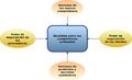
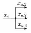
A block diagram is a diagram, in which the principal parts or functions are represented by blocks connected by lines, that show the relationships of the blocks.
Orientation
From left to right

From top to bottom


Circular


Special orientation
-
 Cross orientation
 -
 Waterfall


Building blocks
Number of blocks
-
 One block: a process diagram
 -
 Two blocks
 -
 Three blocks
 -
 Four blocks
 -
 Five blocks
 -
 More blocks


No blocks
-
 Lines and code
 -
 Words as blocks

.svg)
P.S. It is questionable if these diagrams can be considered block diagrams


