CERN Accelerating science

 
\textbf{Left:} Photograph of the \mbox{ScECAL} prototype. The 26 active layers are seen in the clear acrylic support structure. The golden-coloured flat cables are MPPC readout cables and the twisted pair cables in the foreground are connected to the temperature sensors. The white flat cables connect the LEDs of the calibration system. \textbf{Right:} Structure of a type-F detector layer, showing the two mega-strips, each divided into nine strips, the positions of the WLSFs, MPPCs, and the calibration LEDs. The definition of the coordinate system is also shown.
\textbf{Left:} Cross-section of one strip of the type-F mega-strip structure (all dimensions are in mm). The design of type-D mega-strips is the same, except without the hole. \textbf{Right:} Photograph of a MPPC. The package size is $4.2 \times 3.2 \times 1.3~\mathrm{mm}^3$, and the 1600 pixels are contained in an active area of $1 \times 1~\mathrm{mm}^2$.
\textbf{Left:} A typical MPPC output spectrum taken with the LED system, showing the 0-, 1-, 2- and 3-fired-pixel peaks and the results of the fit. \textbf{Right:} Distribution of the measured single pixel signals $d_{\mathrm{high-gain}}$ in the type-F module with an MPPC over-voltage of 2.9~V.
Distribution of the gain ratio $\mathrm{R}_{\mathrm{high/low}}$ in the 30 measured channels.
\textbf{Left:} The MPPC response curve measurement setup. \textbf{Right:} Measured MPPC response curves when using the two types of scintillator strips at different MPPC over-voltages $\Delta V$. The dashed line shows a linear response. Typical effective pixel numbers for the two types are given in Table~\ref{tab:dvalues_lowgain_Npix}.
Sketch of the beam line instrumentation, showing the layout of the four pairs of drift chambers (DC1-4), three trigger counters (T1-3) and the two veto counters (V1-2) relative to the \mbox{ScECAL} prototype. (Not to scale.)
Illustration of the ECAL-based MIP selection. For a given strip in a particular layer L (highlighted on the left), the strips on surrounding layers of the same orientation (right) were required to be consistent (hatched) or inconsistent (filled) with a pedestal signal, depending on the strip position.
\textbf{Left:} ADC distribution for MIP runs, after drift chamber (DC) and ECAL based selections, for a representative type-F strip. \textbf{Right:} Distributions of the measured calibration constants for the two strip types.
\textbf{Left:} Variation of the MIP response with temperature in a typical channel. \textbf{Right:} Distribution of the temperature coefficients $f_{\mathrm{temp}}$ for all channels.
The measured energy distributions of EM shower data in the central region of the \FD\ detector configuration in two runs at a beam momentum of 4~GeV/c. The closed (open) symbols show the response before (after) the application of the temperature correction. The uncorrected curves have been scaled by 50\% to aid visibility. (The cross-talk correction has not been applied.)
\textbf{Left:} Example of MPPC signal when a positron traversed a strip, a neighbouring strip within the same mega-strip or a non-neighbouring (other) strip. \textbf{Right:} Distribution of measured optical cross-talk between neighbouring strips in the same mega-strip.
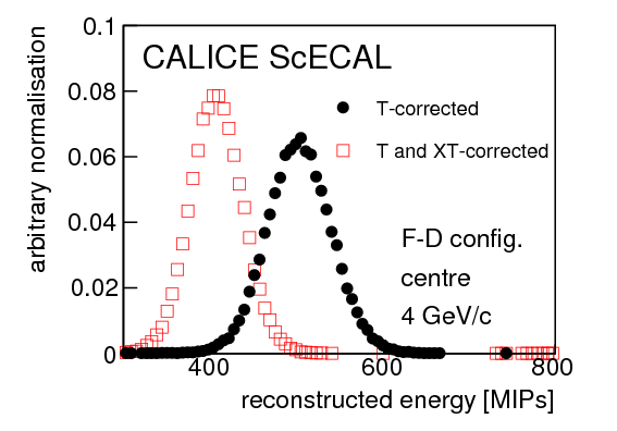
The reconstructed energy after the temperature correction (closed circles) and after an additional cross-talk (XT) correction (open squares), for the same sample of central events collected at 4~GeV/c by the \FD\ detector configuration.
\textbf{Left:} The measured energy spectra of 1--6~GeV/c e$^+$ events collected in the central region, for the \FD\ detector configuration. \textbf{Right:} The dependence of the measured mean energy response on the beam momentum in the uniform region, for the \DF\ detector configuration. Only statistical uncertainties were used in the fit to the linear function (shown as a dotted line).
Deviation from linear energy response measured in the central and uniform regions of both detector configurations. Only statistical uncertainties are shown.
The energy resolutions measured using data taken with 1--6~GeV/c e$^+$ beams in the central and uniform regions of the two detector configurations. The results of the fits described in the text are shown, and the fitted parameters reported in Table~\ref{tab:res_sys_grandsummary}.
Comparison of the stochastic (left) and constant (right) terms of the energy resolution measured in data and simulations in the central (``c'') and uniform (``u'') regions of both detector configurations. The beam energy spread has neither been subtracted from the data, nor included in the simulations. The error bars on the data correspond to the quadratic sum of the statistical uncertainty and all systematic uncertainties except that due to the beam energy spread. The error bars on the simulation points include the statistical uncertainty and systematic effects related to the strip attenuation length.