


Abstract
Sagittarius A* (Sgr A*), the Galactic Center supermassive black hole (SMBH), is one of the best targets in which to resolve the innermost region of an SMBH with very long baseline interferometry (VLBI). In this study, we have carried out observations toward Sgr A* at 1.349 cm (22.223 GHz) and 6.950 mm (43.135 GHz) with the East Asian VLBI Network, as a part of the multiwavelength campaign of the Event Horizon Telescope (EHT) in 2017 April. To mitigate scattering effects, the physically motivated scattering kernel model from Psaltis et al. (2018) and the scattering parameters from Johnson et al. (2018) have been applied. As a result, a single, symmetric Gaussian model well describes the intrinsic structure of Sgr A* at both wavelengths. From closure amplitudes, the major-axis sizes are ∼704 ± 102 μas (axial ratio ∼ ) and ∼300 ± 25 μas (axial ratio ∼1.28 ± 0.2) at 1.349 cm and 6.95 mm, respectively. Together with a quasi-simultaneous observation at 3.5 mm (86 GHz) by Issaoun et al. (2019), we show that the intrinsic size scales with observing wavelength as a power law, with an index ∼1.2 ± 0.2. Our results also provide estimates of the size and compact flux density at 1.3 mm, which can be incorporated into the analysis of the EHT observations. In terms of the origin of radio emission, we have compared the intrinsic structures with the accretion flow scenario, especially the radiatively inefficient accretion flow based on the Keplerian shell model. With this, we show that a nonthermal electron population is necessary to reproduce the source sizes.
Export citation and abstract BibTeX RIS
1. Introduction
The supermassive black hole (SMBH) at our Galactic Center, Sagittarius A* (Sgr A*), is the closest SMBH to the Earth, with a mass of ∼4.1 × 10⁶ M⊙ (Ghez et al. 2008; Genzel et al. 2010). Thanks to its proximity, ∼8.1 kpc (e.g., Gravity Collaboration et al. 2019), Sgr A* has the largest angular size of the Schwarzschild radius (Rs ) among all black holes, ∼10 μas. Therefore it is one of the best laboratories to explore mass accretion onto SMBHs, and it is the other main target besides M 87 for the Event Horizon Telescope (EHT) to resolve the black hole shadow (EHT Collaboration et al. 2019a, 2019b, 2019c, 2019d, 2019e, 2019f).
In very long baseline interferometry (VLBI) observations at centimeter (cm) wavelengths, the structure of Sgr A* is dominated by scatter broadening caused by the ionized interstellar scattering medium (ISM; see, e.g., Rickett 1990; Narayan 1992), which is located at ∼5.8 kpc from Earth (Bower et al. 2014a). As a result, the observed sizes are proportional to λ2 where λ is the observing wavelength (Davies et al. 1976; van Langevelde et al. 1992; Lo et al. 1998; Bower et al. 2004; Shen et al. 2005; Bower et al. 2006; Johnson et al. 2018). The shape has been found to be an asymmetric Gaussian, elongated toward the east–west (i.e., stronger angular broadening; Lo et al. 1985, 1998; Alberdi et al. 1993; Frail et al. 1994; Bower & Backer 1998). While the major and minor axis sizes are subdominant to scattering at ≳1 cm, there are marginal detections of the measured sizes larger than the λ2 scaling at millimeter (mm) wavelengths that indicate the intrinsic size of Sgr A* (Krichbaum et al. 1998; Lo et al. 1998; Doeleman et al. 2001; Lu et al. 2011a). Especially at 1.3 mm, the persistent asymmetric structure of Sgr A* has been also suggested from the proto-EHT observations (Fish et al. 2016; Lu et al. 2018).
In addition to the angular broadening by diffractive scattering, refractive scattering effects introduce substructure in the image that is caused by the density irregularities in the ionized ISM. This substructure appears as "refractive noise" in interferometric visibilities (Goodman & Narayan 1989; Narayan & Goodman 1989; Johnson & Gwinn 2015; Johnson & Narayan 2016), and it was discovered in 1.3 cm observations of Sgr A* by Gwinn et al. (2014). At 7 and 3 mm, nonzero closure phases have been detected that can be interpreted as either the imprint of the intrinsic asymmetry of Sgr A* or the refractive substructure (Brinkerink et al. 2016, 2019; Ortiz-León et al. 2016; Rauch et al. 2016). To better constrain the scattering effects, recently, Psaltis et al. (2018; hereafter P18) suggested a physically motivated scattering model for anisotropic scattering. They introduced magnetohydrodynamics turbulence with a finite inner scale and a wandering transverse magnetic field direction to their simplified model and derived analytic models of expected observational properties, such as the scatter broadening and refractive scintillation. With this model, Johnson et al. (2018; hereafter J18) tightly constrained the scattering parameters such as the power-law index for the density fluctuation in the scattering screen, α, and a finite inner scale of turbulence, rin, using multiwavelength observational data. After that, Issaoun et al. (2019; hereafter I19) showed that the scattering model from J18 provided comparable refractive noise to their observations at 3.5 mm using the Global Millimeter VLBI Array (GMVA) in concert with the phased Atacama Large Millimeter/submillimeter Array (ALMA) in 2017 April.
In this study, we analyze the properties of Sgr A* at 1.349 cm (22.223 GHz; hereafter 1.3 cm and 22 GHz) and 6.950 mm (43.135 GHz; hereafter 7 mm and 43 GHz) with the East Asian VLBI Network (EAVN; Hagiwara et al. 2015; Wajima et al. 2016; An et al. 2018; Cui et al. 2021) observations in 2017 April, by mitigating the scattering effects based on the studies from P18, J18, and I19. The observations have been carried out within two days from the EHT (1.3 mm) and GMVA+ALMA (3.5 mm; I19) campaigns, providing a range of quasi-simultaneous multiwavelength observations, which is crucial for constraining the physical parameters. To this end, we report the flux densities and intrinsic structures of Sgr A* at both wavelengths.
The structure of Sgr A* can provide an important hint of its emission model. There is a long debate about the dominant emission source of Sgr A*, whether it is an accretion flow or a jet. While there are many theoretical predictions (e.g., Mościbrodzka et al. 2014) and indirect evidence (e.g., Brinkerink et al. 2015) of a possible jet from Sgr A*, a jet-like structure has not been resolved yet. So, we first find the most probable model of an accretion flow scenario, and determine if it can solely explain the observed results in which circumstances. For this purpose, we have compared the measured intrinsic structure of Sgr A* with a radiatively inefficient accretion flow (RIAF) based on the Keplerian shell model (Falcke et al. 2000; Broderick & Loeb 2006; Pu et al. 2016; Kawashima et al. 2019) and found that the thermal-nonthermal electron population is necessary to reproduce the observational results. A similar comparison has been carried out with the spectral energy distribution (SED; e.g., Özel et al. 2000; Yuan et al. 2003) and with a theoretical structure at 230 GHz (Chael et al. 2017; Mao et al. 2017), but has not been done with the structure at a lower frequency range (i.e., 22 and 43 GHz). Note that our analysis is based on a recent study of the electron energy spectrum in an accretion flow (Broderick et al. 2011; Pu et al. 2016), so it does not rule out the possible jet scenario, which is beyond the scope of this paper.
In this paper, we begin with the outline of our observations and data processing in Section 2. Next, in Section 3, the imaging and model-fitting procedures are described. In Section 4, the overall results including the wavelength dependence and its implication for the EHT imaging are presented. In Section 5, the importance of nonthermal electron components for an accretion flow model to explain our results is discussed. Lastly, we summarize our findings in Section 6.
2. Observations and Data Reduction
The EAVN consists of the KaVA (KVN 32 and VERA 33 Array; e.g., Niinuma et al. 2015; Hada et al. 2017; Park et al. 2019) and additional East Asian telescopes (e.g., Tianma 65 m, Nanshan 26 m, and Hitachi 32 m telescopes; Cui et al. 2021). As a part of the KaVA/EAVN Large Program (e.g., Kino et al. 2015), which intensively monitors Sgr A* within a ≲1 month time interval, several EAVN observations at 1.3 cm and 7 mm were carried out in 2017 April. In this study, we present the results of two observations (2017 April 3 and 4) close to the other global VLBI campaigns: GMVA+ALMA at 3.5 mm (2017 April 3) and EHT at 1.3 mm (2017 April 5–11; see Table 1). The EAVN data are recorded with a 256 MHz (32 MHz × 8 channels) total bandwidth. The on-source time for Sgr A* and a calibrator, NRAO 530, is ∼160 and ∼30 minutes, respectively.
Table 1. EAVN and the Quasi-simultaneous Observations
| Array | Date (2017) | λ (cm) | Reference |
|---|---|---|---|
| EAVN | Apr 03 | 1.349 | This work |
| EAVN | Apr 04 | 0.695 | This work |
| GMVA+ALMA | Apr 03 | 0.35 | I19 |
| EHT | Apr 05–11 | 0.13 | ⋯ |
Note. From left to right, the observing array, date, wavelength, and references.
Download table as: ASCIITypeset image
The KaVA and Tianma 65 m (TIA) sites participated in the observations at both 1.3 cm and 7 mm (Figure 1). At 1.3 cm, the Nanshan 26 m (Urumqi, UR), and Hitachi 32 m (HT) telescopes additionally joined. However, UR provides the baseline length of ∼100–380 Mλ that is already dominated by refractive scattering noises (see Section 3), so the fringes were not detected. The HT had a severe problem with its antenna gain, so it was flagged out.

Figure 1. The u−v coverage of EAVN observations at 1.3 cm (left) and 0.7 cm (right). The KaVA observations with a successful detection (S/N > 5; cyan) and flagged points (gray) are shown. TIA provides the longest baselines (red). Each point has been averaged within a 30 s interval.
Download figure:
Standard image High-resolution imageThe data were calibrated using the NRAO Astronomical Imaging Processing System (AIPS; Greisen 2003). The cross-power spectra were first normalized using the auto-correlation power spectra (ACCOR in AIPS), and a multiplicative correction factor of 1.3 was applied to all data to correct the quantization loss in the Daejeon hardware correlator (Lee et al. 2015). For the amplitude calibration, we used the system temperature and antenna gain curve information (a priori calibration method; APCAL in AIPS) for the 1.3 cm data. As for the 7 mm data, the SiO maser lines from OH 0.55−0.06 and VX Sgr were instead used, which provided a better gain correction (template spectrum method; ACFIT in AIPS). Cho et al. (2017) have confirmed that the template spectrum method can derive a more realistic antenna gain curve as a function of the elevation than the a priori calibration method so that a better accuracy of the amplitude calibration can be achieved. Note that it is also possible to use the H2O maser line at 1.3 cm, but the nearby maser source, Sgr B2, has an extended maser spot distribution of up to ∼120'', which is much broader than the beam size of TIA (e.g., FWHM ∼ 44'' at 1.3 cm) so that it may provide relatively worse results (Cho et al. 2017). The phase calibration was implemented with three steps: (1) the ionospheric effect and parallactic angle corrections 34 (VLBATECR and VLBAPANG in AIPS), (2) instrumental phase and delay offset correction using the best fringe fit solutions of a fringe tracer, and (3) the global fringe search (FRING in AIPS). Note that VLBATECR was not applied for the 7 mm data since the ionospheric effect was less severe. The correction of VLBAPANG was also small for KaVA data such that the visibility phases were mostly consistent before and after the calibration. As a result, the phase delay and fringe frequency solutions were successfully obtained with a signal-to-noise ratio (S/N) > 5. The bandpass calibration was done in two steps: (1) for the amplitudes using the total power spectra, and (2) for both amplitudes and phases using the cross-power spectra of Sgr A*.
After the calibrations, the visibilities at lower elevations < 5° at either telescope of a baseline were flagged. To correct the residual amplitudes offset across the frequency channels (8 channels), both the multichannel data and channel-averaged data were used. First, a Gaussian model was obtained from the channel-averaged data. The multichannel data were then self-calibrated with the Gaussian model and averaged across the entire bandwidth. The frequency-averaged visibilities were coherently time averaged over 30 s, and the outliers were flagged.
3. Imaging and Model Fitting
The scattering effects toward Sgr A* can be approximated by a single thin phase screen (e.g., Goodman & Narayan 1989; Narayan & Goodman 1989; Narayan 1992). The interferometric visibility of a scattering kernel is ![${\rm{\exp }}\left[-\tfrac{1}{2}{D}_{\phi }(b/(1+D/R))\right]$](https://content.cld.iop.org/journals/0004-637X/926/2/108/revision1/apjac4165ieqn2.gif) , where Dϕ
is the phase structure function of the scattering screen, b is the baseline length, D is the distance between Earth and the scattering screen, and R is the distance between Sgr A* and the scattering screen (J18). For the baseline lengths b ≲ (1 +D/R)rin, where rin is a finite inner scale of interstellar turbulence, the phase fluctuations are smooth so that the scatter broadening provides a Gaussian blurring (i.e., diffractive scattering dominated). At the baselines longer than this, by contrast, both the scattering kernel and the refractive scattering noises introduce the non-Gaussian features (P18, J18; see also Section 3.3). Therefore we use the "short" baselines where they can be fitted with a Gaussian model avoiding the noise biases. With D = 2.7 kpc, R = 5.4 kpc, and rin = 800 km (J18), the "short" baselines are found to be 91 and 176 Mλ at 1.3 cm and 7 mm wavelengths, respectively. Note however that the nonlinear imaging reconstructions use the full baseline ranges (see Section 3.1). In addition, the S/N cutoffs are also applied, for instance the S/Nth > 3 and S/Nref > 4 where Nth and Nref are thermal noise and refractive scattering noise, respectively (e.g., J18; see Section 3.3 for the refractive noise derivation). This corresponds to the ensemble-average scattering limit (see Goodman & Narayan 1989; Narayan & Goodman 1989), where the scattering effects are the convolution of a scattering kernel onto an unscattered image.
, where Dϕ
is the phase structure function of the scattering screen, b is the baseline length, D is the distance between Earth and the scattering screen, and R is the distance between Sgr A* and the scattering screen (J18). For the baseline lengths b ≲ (1 +D/R)rin, where rin is a finite inner scale of interstellar turbulence, the phase fluctuations are smooth so that the scatter broadening provides a Gaussian blurring (i.e., diffractive scattering dominated). At the baselines longer than this, by contrast, both the scattering kernel and the refractive scattering noises introduce the non-Gaussian features (P18, J18; see also Section 3.3). Therefore we use the "short" baselines where they can be fitted with a Gaussian model avoiding the noise biases. With D = 2.7 kpc, R = 5.4 kpc, and rin = 800 km (J18), the "short" baselines are found to be 91 and 176 Mλ at 1.3 cm and 7 mm wavelengths, respectively. Note however that the nonlinear imaging reconstructions use the full baseline ranges (see Section 3.1). In addition, the S/N cutoffs are also applied, for instance the S/Nth > 3 and S/Nref > 4 where Nth and Nref are thermal noise and refractive scattering noise, respectively (e.g., J18; see Section 3.3 for the refractive noise derivation). This corresponds to the ensemble-average scattering limit (see Goodman & Narayan 1989; Narayan & Goodman 1989), where the scattering effects are the convolution of a scattering kernel onto an unscattered image.
We add 10% of visibility amplitudes in quadrature as a systematic error for all KaVA data, which is a typical amplitude gain uncertainty of cm−mm VLBI observations (e.g., Cho et al. 2017). However, for TIA data at 1.3 cm, we add 30% of the visibility amplitudes as a systematic error to account for residual bandpass, relatively poorer system temperature measurements, and larger pointing uncertainties (see, e.g., Cui et al. 2021 and the EAVN status report 35 ).
To confirm the single Gaussian approximation, we first check the closure phases, which are the sum of visibility phases of three baselines forming a triangle. Since the closure phases are independent of the phase gain uncertainties, these are robust VLBI observables together with the closure amplitudes (e.g., Thompson et al. 2017; EHT Collaboration et al. 2019c; Blackburn et al. 2020; see also Section 3.2). We compare the closure phases of Sgr A* with a nearby calibrator, NRAO 530. NRAO 530 shows an extended structure toward the north and its closure phases are correspondingly different from zero, especially along with triangles that include long baselines (e.g., ISG-KYS). That said, the closure phases of Sgr A* are consistent with zero (Figure 2), which indicates a symmetric source structure. Therefore, we model the data with a single, elliptical Gaussian within a "short" baseline range (i.e., ensemble-average image).

Figure 2. Closure phases of Sgr A* (gray) and NRAO 530 (yellow) at 1.3 cm (first and second rows) and 0.7 cm (third and fourth rows). From left to right, the corresponding baselines toward Sgr A* in the u−v plane (colored points), closure phases as a function of observing time, and a histogram of the closure phases are shown. Each point has been averaged within 30 s. The time-averaged closure phase,  , is shown in each legend. The uncertainty represents the standard deviation.
Download figure:
Standard image High-resolution image3.1. Self-calibration
For the self-calibration, which corrects the station-based gain uncertainties, we reconstruct the image of Sgr A* using two different approaches: (1) Gaussian model fitting to the complex visibilities using the modelfit in DIFMAP software (Shepherd et al. 1994), and (2) imaging based on both the complex visibilities and closure quantities using the regularized maximum likelihood (RML) method.
As for the two-dimensional (2D) Gaussian model fitting, a single, elliptical Gaussian model is fitted within the "short" baseline range, ≲91 and ≲176 Mλ at 1.3 cm and 7 mm wavelengths, respectively. Note that these are roughly half of the longest baseline lengths where the fringes toward Sgr A* have been successfully detected. Nevertheless, we can still derive gain corrections for all stations using only the data in this range since every station has at least one independent closure amplitude on most of the scans.
For the imaging via RML method, we use the SMILI software library 36 (Akiyama et al. 2017a, 2017b, 2019). SMILI has more flexibility in the data products used for imaging, so this enables us to use the robust closure quantities. To reconstruct the observed structure of Sgr A*, therefore, both the visibility amplitudes and closure quantities are used. For SMILI imaging, a full baseline range has been used so that the refractive substructures are also reconstructed and the visibilities are self-calibrated with this model. Note that the refractive noises are baseline-based so that they have a minor effect on the derived station-based gain uncertainties. The imaging parameters have been searched for the regularizers of ℓ1 norm and the total squared variation (TSV), which represent the image sparsity and smoothness, respectively, in a range of [0.01, 0.1, 1.0, 10, 100] (see Appendix A for SMILI imaging and its regularizers). The fixed values of ℓ1 prior = 2 and field of view = 12.8 mas (128 pixels × 0.1 mas pixel−1) are used. Based on the quadratic sum of χ2 of closure quantities, the fiducial parameters for Sgr A* are found as [ℓ1 norm, TSV] = [0.1, 0.1] and [0.01, 0.1] at 1.3 and 0.7 cm, respectively. For NRAO 530, [ℓ1 norm, TSV] = [0.01, 0.1] and [0.1, 1.0] at 1.3 and 0.7 cm, respectively.
As a result, the derived multiplicative gains for each telescope are well consistent between two different methods (Figure 3). For comparison, the gain solutions from NRAO 530 are also derived by the SMILI imaging. Figure 4 shows the self-calibrated visibility amplitudes with the Gaussian model fitting. Note that the non-Gaussian noise appears at the longer baselines. The sizes of the ensemble-average image are then obtained by Gaussian model fitting onto the self-calibrated visibility amplitudes within the "short" range: ∼2.6 × 1.4 mas (position angle ∼82°–83°) and ∼0.7 × 0.4 mas (position angle ∼83°–85°) at 1.3 cm and 7 mm, respectively (see Table 2). These are consistent with the scattering dominated size of Sgr A*, with the asymptotic Gaussian scattering kernel of (1.380 ± 0.013)λ2 (mas) for the major axis and (0.703 ± 0.013)λ2 (mas) for the minor axis where λ is the observing wavelength in cm (J18). For instance, the asymptotic Gaussian scattering kernel sizes at 1.3 and 0.7 cm are ∼2.51 × 1.28 mas and ∼0.67 × 0.34 mas respectively, which are slightly smaller than the measured ensemble-average sizes. Figure 5 shows the reconstructed images of NRAO 530 and Sgr A* from SMILI imaging. Note that the Sgr A* images show scattered, not intrinsic, structure. The contour and color maps show the beam convolved structure. The ellipses at the center of the Sgr A* image show the best-fitting 2D Gaussian model of the ensemble-average (broken line) and intrinsic (solid line, cross) structure of Sgr A*, from the closure amplitudes (see Section 4.1 and Table 2).

Figure 3. Multiplicative amplitude gain correction factors for each station at 1.3 cm (upper) and 0.7 cm (lower). The median values from Gaussian model fitting (red, circle) and SMILI imaging (blue, square) for Sgr A* are shown. The gain corrections for NRAO 530 from SMILI imaging are also shown for comparison (green, triangle). The uncertainties are 1σ standard deviations of the time-dependent amplitude gain correction factors.
Download figure:
Standard image High-resolution image
Figure 4. Top: normalized correlated flux density of Sgr A* at 1.3 cm (left) and 0.7 cm (right). The gray circles are visibility amplitudes after self-calibration. The blue lines are the Gaussian scattering kernel toward the major axis (solid line) and minor axis (dashed line). The cyan-colored, broken dotted vertical line shows the "short" range at each wavelength. The magenta points are the derived refractive noise, σref. Bottom: the ratio of the residual of the visibility amplitudes and the fitted model amplitudes, over the thermal noise. Each point has been 5 minutes averaged for clearer visualization.
Download figure:
Standard image High-resolution image
Figure 5. Observed structure of NRAO 530 (upper) and Sgr A* (lower), at 1.3 cm (left) and 0.7 cm (right). The restoring beam is shown in the lower left side of each panel. The contour levels are (1, 2, 4, 8, 16, 32, and 64)% of peak intensity. The blue ellipses with broken lines and solid lines (with cross) at the center of Sgr A* images show the best-fitting Gaussian model of the ensemble-average and intrinsic structure, respectively, derived from closure amplitudes (see Table 2). As for the NRAO 530, the extended jet feature is well consistent with the one seen in previous studies (e.g., Lu et al. 2011b; Jorstad et al. 2017).
Download figure:
Standard image High-resolution imageTable 2. Gaussian Model Fitting Results
| λ (cm) | Method | S (Jy) (Jy) |
 (μas) (μas) |
 (μas) (μas) | ren |
 (deg) (deg) |
 (μas) (μas) |
 (μas) (μas) | rint |
 (deg) (deg) |
|---|---|---|---|---|---|---|---|---|---|---|
| 1.349 | Gfit/Amp | 1.05 ± 0.11 | 2621.1 ± 26.4 | 1424.4 ± 13.3 | 1.84 ± 0.02 | 82.8 ± 0.4 | 827.1 ± 93.4 | 630.8 ± 52.6 | 1.31 ± 0.19 | 95.6 ± 23.4 |
| SMILI/Amp | 1.04 ± 0.10 | 2617.9 ± 26.4 | 1412.7 ± 13.5 | 1.85 ± 0.02 | 82.8 ± 0.4 | 814.8 ± 93.3 | 602.6 ± 53.1 | 1.35 ± 0.19 | 94.6 ± 23.4 | |
| CA | ⋯ | 2585.1 ± 27.9 | 1383.3 ± 30.2 | 1.87 ± 0.05 | 82.5 ± 0.6 | 704.3 ± 102.0 |

|

| 95.5 ± 27.8 | |
| 0.695 | Gfit/Amp | 1.36 ± 0.14 | 715.6 ± 8.6 | 414.9 ± 8.5 | 1.73 ± 0.04 | 84.2 ± 0.7 | 294.6 ± 23.6 |

| 1.28 ± 0.11 | 109.6 ± 8.9 |
| SMILI/Amp | 1.30 ± 0.13 | 727.2 ± 8.6 | 425.7 ± 8.2 | 1.71 ± 0.04 | 85.6 ± 0.7 | 331.1 ± 23.4 | 235.5 ± 12.0 | 1.40 ± 0.11 | 112.7 ± 7.3 | |
| CA | ⋯ | 720.8 ± 9.0 | 412.0 ± 19.8 | 1.75 ± 0.09 | 83.2 ± 1.0 | 300.0 ± 24.8 |

| 1.28 ± 0.20 |

| |
Note. Overall results of total flux density, and scattered and unscattered size of Sgr A* at 1.3 and 0.7 cm wavelengths. From left to right: observing wavelength, imaging/model-fitting method, total flux density, ensemble-average (i.e., scattered) structure and intrinsic (i.e., unscattered) structure. The results are from three different methods: self-calibration with the Gaussian model fitting and size fitting on the visibility amplitudes (Gfit/Amp), self-calibration with the SMILI imaging and size fitting on the visibility amplitudes (SMILI/Amp), and the size fitting on the log closure amplitudes (CA). See Section 3 for more details. The subscripts are specific frequency (ν), major axis (maj), minor axis (min), and position angle (PA). The superscripts are total flux density (tot), ensemble-average image properties (en) and intrinsic properties (int). The ±1σ uncertainties are shown considering the possible error components (see Appendix B), except the total flux density, which shows the 10% of each measurement.
Download table as: ASCIITypeset image
3.2. (Log) Closure Amplitudes
While the best-fitting model to visibility amplitudes can provide reasonable antenna gain solutions, it may be still difficult to take into account all possible gain uncertainties (Bower et al. 2014b). To overcome this, we fit the 2D Gaussian model to the log closure amplitudes, which are robust observables free from the amplitude gain uncertainties. Note however that it is difficult to constrain the flux density with only the closure amplitudes so it is complementary to the self-calibration and vice versa.
The closure amplitudes of four different stations (i, j, k, l) are defined as the ratios of visibility amplitudes so that the station-based amplitude gain errors are canceled out. Three different closure amplitudes can be formed with any set of four stations, and two of them are independent (e.g., Chael et al. 2018),

where C is the closure amplitude at each quadrangle and ∣V∣ is the visibility amplitude at each baseline. The number of independent closure amplitudes at a certain time range is N(N − 3)/2, where N is the number of stations. There are a number of ways to form the independent closure amplitudes, and it is important to select the set where the S/N is high enough to limit the correlated noise biases (Blackburn et al. 2020).
Using SMILI, we form the independent closure amplitudes from the visibilities within the aforementioned "short" range. The closure amplitudes of the 2D Gaussian model are formed in the same way. The best-fitting model is found using a Monte Carlo method
37
on the log closure amplitudes to avoid the biases and to symmetrize the numerator and denominator in closure amplitudes (e.g., Chael et al. 2018; Blackburn et al. 2020). Note that the closure amplitudes are insensitive to the total flux density so it is not fitted but rather given as the value obtained from the self-calibrations. Therefore three parameters of the ensemble-average image, major-axis size ( ), axial ratio (
 /
/ ), and position angle (
 ) have been estimated. From this, we find that the results are consistent with the amplitude self-calibration (Table 2). This demonstrates that the reconstructed models from imaging and 2D Gaussian model fitting properly correct the station-based gain uncertainties.
3.3. Scattering Kernel Model and Deblurring
According to the physically motivated scattering model, the scattering kernel is no longer a simple (anisotropic) Gaussian and is not purely proportional to the square of observing wavelengths (P18). Adopting the P18 model, therefore, we have developed the scatter model module of the SMILI.
38
This is almost identical with the stochastic optics module of the eht-imaging software library
39
(Johnson 2016; Chael et al. 2018), and the scattering parameters have been adopted from J18 (e.g.,  , rin = 800 ±200 km). Then the self-calibrated, ensemble-average visibility amplitudes and closure amplitudes are divided by the derived scattering kernel (i.e., deblurring), which corresponds to the deconvolution in the image domain.
To estimate the refractive noise, we first generate the synthetic images (e.g., intrinsic structure of Sgr A* from J18) and scatter them ∼1000 times each with a randomly generated phase screen using the stochastic optics module. The corresponding visibilities are then obtained by Fourier transform at each u, v point of the EAVN data. As the number of iteration increases, the standard deviation of real and imaginary parts of the visibilities converge to the rms refractive noise at each u, v point. The derived refractive noise is used to constrain the noise-dominated visibilities, through the aforementioned S/Nref cutoffs.
4. Results
Here, we summarize the observational results. The obtained intrinsic sizes of Sgr A* and its wavelength dependence are presented in Section 4.1. In Section 4.2, the flux densities and spectral indices of Sgr A* are shown.
4.1. The λ Dependent Intrinsic Size of Sgr A*
The intrinsic structure of Sgr A* is found from the Gaussian model fitting to the deblurred visibility amplitudes or closure amplitudes. While the "observed" size is angularly broadened by the diffractive scattering, the "intrinsic" size is scatter deblurred so that it is free from the angular broadening. The Monte Carlo method is used to find the optimal values of three free parameters: "intrinsic" major-axis size ( ), axial ratio (
 /
/ ), and position angle (
 ). Note that the scattering-deblurred amplitudes are normalized with the total flux density,
  . The axial ratio of major and minor axis size is ∼1.2–1.4 and the PA is ∼95°–113°, so the intrinsic sizes of Sgr A* at both wavelengths look slightly elongated in the east–west direction. The PA is consistent with that of previous studies (e.g., ∼105° from Markoff et al. 2007; ∼95° from Bower et al. 2014b), and roughly aligned with the orientation of the large-scale X-ray emission as well (Li et al. 2013). Considering the uncertainties, however, the axial ratios are consistent with unity within the ≲3σ uncertainty range (Table 2). See Appendix B for more details of the uncertainty estimates. While this is consistent with results from J18, Bower et al. (2014b) reported the axial ratio of ∼2.8 coming from the smaller minor axis size at 7 mm, ∼126 μas. This may indicate the possible time variation of the minor axis size of Sgr A*, and it will be investigated through long-term monitoring observations (e.g., X. Cheng et al. 2022, in preparation). Note that the results from different methods are well consistent with each other within the uncertainties. For later discussions, the results from model fitting onto the log closure amplitudes are used since this provides a more robust measurement and conservative uncertainties.
Together with the intrinsic size of Sgr A* at 3.5 mm, which has been measured in a ∼1 day separation from our EAVN observations (I19), we fit the wavelength-dependent intrinsic size with a power law,  where θ1mm is the source size at 1 mm, λmm is the observing wavelength in mm, and
  is the power-law index that characterizes the intrinsic properties of the emission region as a function of observing wavelength. As a result, the measured sizes of Sgr A* at 13, 7, and 3.5 mm are well fit with a single power law (see Figure 6). The derived power-law index, = 1.2 ± 0.2, is consistent with the previous measurements of ∼ 1.2–1.3 (e.g., Falcke et al. 2009; Lu et al. 2011a; Ortiz-León et al. 2016; Brinkerink et al. 2019) and ∼ 1.0–1.1 (e.g., Shen et al. 2005, J18). Note that the derived from size fitting results on the visibility amplitudes, which are self-calibrated with the Gaussian model fitting (Gfit/Amp) and SMILI imaging (SMILI/Amp), are 1.4 ± 0.2 and 1.3 ± 0.2, respectively. These are consistent with the result from closure amplitudes (CA) within each uncertainty. The uncertainties of our fitted results are relatively large since we only use the (quasi-)simultaneous observations, so that the number of data points is small. To better constrain the size−wavelength relation, therefore, the intrinsic sizes at more various wavelengths are necessary, especially at 2 mm and ≳2 cm. In addition, the quasi-simultaneous campaigns at a variety of wavelengths, as we have achieved in 2017 together with the GMVA+ALMA and EHT, are further required since the (marginal) size variation of Sgr A*, especially at 7 mm, has been found (e.g., Bower et al. 2004; Akiyama et al. 2013; Zhao et al. 2017).

Figure 6. Intrinsic size of Sgr A* as a function of wavelength. The squares and circles show the major and minor axis sizes (i.e., FWHM), respectively. While the filled markers are the results from this work, the open markers show the previous experiments at 3.5 (I19) and 1.3 mm (J18; Doeleman et al. 2008 in green, diamond). The markers are offset slightly in wavelength for a clearer visualization. The power-law fitting results are shown: toward the major axis (red, broken dotted line) and minor axis (blue, broken line) sizes. Note that only the 3.5, 7, and 13 mm wavelengths are used for the fitting, which are the quasi-simultaneous measurements in 2017 April. The 1.3 mm results are shown for comparison (e.g., the extrapolated sizes). The horizontal broken line (gray) shows the expected black hole shadow diameter at Sgr A* (∼51 μas; e.g., J18).
Download figure:
Standard image High-resolution imageFrom the best-fitting results, the extrapolated size at 1.3 mm is found to be  and
and  toward the major and minor axis, respectively. This is close to the previous measurements with the EHT (e.g., 37 ± 13 μas from Doeleman et al. 2008; 41–44 μas from Fish et al. 2011; 51–52 μas from Lu et al. 2018; 56 ± 7 μas and
  for the major and minor axes, respectively, from J18). Note however that the structure of Sgr A* at 1.3 mm may be non-Gaussian (e.g., Johnson et al. 2015; Fish et al. 2016; Lu et al. 2018) so that the extrapolated size can be a hint for high-resolution imaging, for instance with the EHT.
4.2. Flux Densities and Spectral Indices
At radio to submillimeter wavelengths, Sgr A* shows an inverted (time-averaged) spectrum, Sν ∝ νβ (β > 0; e.g., Duschl & Lesch 1994; Morris & Serabyn 1996; Serabyn et al. 1997; Falcke et al. 1998; Krichbaum et al. 1998; Zhao et al. 2001), where Sν is specific flux density, ν is the observing frequency, and β is the spectral index. The spectrum peaks and cutoffs are shown at 230–350 GHz (e.g., Yusef-Zadeh et al. 2006; Bower et al. 2015), which are due to the transition of synchrotron emission from being optically thick to thin. This implies that Sgr A* has a stratified, self-absorbed geometry of plasma, either a jet or an accretion flow, and the (sub)millimeter emission arises from several Rs (e.g., Melia 1992, 1994). At millimeter/submillimeter wavelengths, in addition, there exists a break in the spectrum so called the "millimeter/submillimeter bump," which deviates from a single power-law index. This may be explained by the compact components in the acceleration zone of a jet, or the thermal electrons in an accretion flow (e.g., Lu et al. 2011a).
In our observations, the total flux densities are ∼1.0 and 1.3 Jy at 22 and 43 GHz, respectively (see Table 2). With the intrinsic major-axis size, we can derive a lower limit of the brightness temperature of Tb ≳ 0.4–0.5 × 10¹⁰ K and ≳0.8–1.0 × 10¹⁰ K at 1.3 and 0.7 cm, respectively. Together with the flux density at 86 GHz, ∼2 Jy (I19), the spectral index of Sgr A* within the three frequencies is derived as β = 0.39 ± 0.02. Considering the millimeter/submillimeter bump at ≳43 GHz, at the same time, we derive the values of β for 22−43 GHz and 43−86 GHz separately and find β ≈ 0.29 ± 0.10 and 0.44 ± 0.16, respectively. Note that the smaller number of points leads to larger uncertainties. Nevertheless, the results are well consistent with those of historical studies. For instance, while β ∼ 0.24–0.3 up to ∼43 GHz (e.g., Falcke et al. 1998; Krichbaum et al. 1998; Lu et al. 2011a; Bower et al. 2015), β ∼ 0.5 at ≳43 GHz (Falcke et al. 1998; Bower et al. 2015).
With the derived spectral indices, the flux density at 230 GHz can be extrapolated assuming the same spectral index up to 230 GHz and the turnover frequency between 230 GHz (e.g., Yusef-Zadeh et al. 2006; Bower et al. 2015) and 1 THz (Bower et al. 2019). For the spectral index of the single power law, β ∼ 0.39, the extrapolated flux density at 230 GHz is ∼2.73 Jy. The lower and upper limits of the extrapolated flux densities are then estimated from the spectral indices for the lower and higher frequency ranges (i.e., β ∼ 0.29 and 0.44), respectively. With this, the compact flux density of Sgr A* at 1.3 mm in 2017 April, observed with the EHT, is expected to be  Jy.
Jy.
5. Nonthermal Electron Emission Models
The details of the physical nature of radio emission from Sgr A* remain elusive. Here, we discuss the emission models and indications of the existence of nonthermal electrons to explain the wavelength-dependent intrinsic sizes of Sgr A*. Pioneering work by Özel et al. (2000) discussed a possible explanation of the prominent shoulder (excess) at ≲100 GHz in the spectral energy distribution (SED) of Sgr A* by a hybrid thermal-nonthermal electron population. The SED discussed in Özel et al. (2000), however, was the assembly of nonsimultaneously measured radio flux values from mostly single dish data so that it potentially contained a significant amount of emission originating from the extended region around Sgr A*. Therefore, it is not entirely clear whether such a hybrid thermal-nonthermal electron population is really required or whether the observed excess is just a superposition of emission from extended regions that cannot reflect intrinsic properties of Sgr A*.
In this work, we obtain the VLBI-measured quasi-simultaneous intrinsic sizes and the corresponding flux densities at 13, 7, and 3.5 mm for the first time. Using these data, we discuss the necessity of a nonthermal electron population in Sgr A*. Note that the question about the dominant radio emission model of Sgr A*, either an accretion flow or a jet, is still open for debate. Since there is no clear observational evidence of jet eruption in Sgr A* on VLBI scales yet, we will focus on the accretion flow model in this section. The possible jet model can be compared with the results from I19. 40
We examine the theoretical images of radiatively inefficient accretion flow (RIAF) based on the Keplerian shell model (Falcke et al. 2000; Broderick & Loeb 2006; Pu et al. 2016; Kawashima et al. 2019). The radiative transfer is solved using the general relativistic, ray-tracing radiative transfer (GRRT) code RAIKOU (Kawashima et al. 2019, 2021a, 2021b). The cyclo-synchrotron emission/absorption via thermal electrons (Mahadevan et al. 1996) and synchrotron processes via nonthermal electrons (see, e.g., Dexter 2016) are incorporated. For the sake of simplicity, the angle between the ray and magnetic field θB is assumed to be  for the calculation of emission/absorption via the nonthermal electrons, which corresponds to the average for the isotropic, random magnetic field.
We set the number density of thermal electrons ne,th, that of nonthermal electrons ne,nth, electron temperature Te, and the magnetic field B at (r, θ), where r and θ are the spherical radius and the polar angle in the Schwarzschild coordinates, in the Keplerian shell model as follows:

Here, mp is the proton mass, rg(=GM/c2) is the gravitational radius, and G, M, and c are the gravitational constant, the black hole mass, and the speed of light, respectively. We assume the rg
with a mass M = 4.1 × 10⁶
M⊙ and distance 8.1 kpc. The scale height of the accretion flow is set to be H/R = 0.5, where R is the cylindrical radius  . The acceleration mechanism of the electrons is uncertain, although they may be accelerated by the magneto-rotational instability turbulence (Lynn et al. 2014), magnetic reconnection (Hoshino 2013; Ball et al. 2018; Werner et al. 2018; Ripperda et al. 2020) and/or by other mechanisms. Therefore we simply assume the energy spectrum of the nonthermal electrons to be a single power-law distribution ∝ γ−3.5 in the range 102 ≤ γ ≤ 106, where γ is the Lorentz factor of the electrons whose power-law index and the minimum Lorentz factor are the same as those in Broderick et al. (2011) and Pu et al. (2016). Here, a slightly extended spatial distribution of nonthermal electrons ne, nth ∝ r−1.75 (in previous works, e.g., Broderick et al. 2011 and Pu et al. 2016, ∝ r−2.02) is found from our observational data. Note that this is mainly due to the smaller uncertainty of our results (Figure 7) and the main conclusion regarding the existence of nonthermal electron population is not strongly affected by the small difference. The consequent higher fluxes at 1.3 cm and 7 mm require the spatially extended emission region due to synchrotron emission via nonthermal electrons. Note that this is broadly applicable, and is not only valid for the parameter set chosen above, where the Keplerian shell model holds. As is shown later, this can be confirmed by comparing the radius of the outer edge of the accretion flow and the observed size at each wavelength.
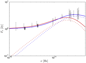
Figure 7. Theoretical SEDs for the models with i = 20° (red) and 60° (blue). The thick solid and thin dashed lines represent the results taking into account thermal plus nonthermal electrons and thermal electrons only, respectively. The black data points show the observation data at 22 and 43 GHz in this work. The gray data points display the previous observational data (Falcke et al. 1998; Bower et al. 2015).
Download figure:
Standard image High-resolution imageFigure 8 displays the resultant images of the Sgr A* accretion flow. The intensity is shown in log scale. All of the models with only thermal electrons show very compact core images. For example, at 1.3 cm, the intensity drastically decreases outside the diameter of ∼300 μas, i.e., the intensity outside this diameter is lower than the peak intensity by an order of magnitude, and this diameter is too small compared with the measured one. This compact emission region is a consequence of the low synchrotron frequency in the outer region as explained in the next paragraph. By contrast, the synchrotron frequency can be higher than ∼10 GHz if nonthermal electrons are assumed, so that the resultant images for the models with nonthermal electrons show a larger emission region whose diameter is ∼500 μas. This is qualitatively consistent with a pioneering theoretical work assuming a one-dimensional plasma structure (Özel et al. 2000). This indicates that our observed images provide the direct detection of nonthermal electrons, and a sufficient amount of nonthermal electrons should exist in the outer region, as has been proposed by the previous theoretical works focusing on the spatially unresolved SED (e.g., Yuan et al. 2003). 41 The image enlargement due to synchrotron emission via nonthermal electrons is also consistent with horizon-scale theoretical images at 230 GHz (Chael et al. 2017; Mao et al. 2017). Figure 7 shows a comparison between the observed flux densities and our theoretical SEDs. We find that the nonthermal synchrotron emission can well explain the overall excess component below 100 GHz, including at 22 and 43 GHz observed by the EAVN.

Figure 8. Theoretical images of accretion flow in Sgr A* observed at the wavelength 1.3 cm (left), 0.7 cm (middle), and 0.3 cm (right), based on the Keplerian shell model. The viewing angle i is (a) 20° and (b) 60°. The synchrotron emission/absorption processes are calculated taking into account thermal electrons only (top) and both thermal and nonthermal electrons (bottom).
Download figure:
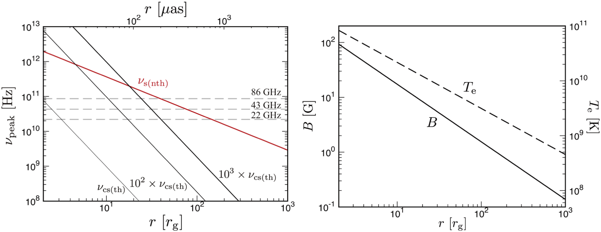
Standard image High-resolution imageWe further interpret the image size of the theoretical models shown in Figure 8 by considering the peak frequency of synchrotron and cyclo-synchrotron emissivity. The peak frequency of synchrotron and cyclo-synchrotron emissivity νpeak, is generally expressed in terms of B, Te (for thermal electrons), and minimum Lorentz factor  (for nonthermal electrons with the power-law index greater than 2) in the accretion flow. With the Keplerian shell model, νpeak can then be expressed as a function of the accretion flow radius. One can roughly estimate the outer edge of the bright core by the radius at which an observing frequency is equal to that of the emissivity peak frequency, since the emission will become drastically faint if the observing frequency is greater than νpeak. Figure 9 (left) shows the peak frequency of cyclo-synchrotron emissivity via thermal electrons and synchrotron emissivity via nonthermal electrons as a function of the emitting radius according to our Keplerian shell model. The corresponding spatial distributions of Te and B are shown in Figure 9 (right). The peak frequency of our nonthermal synchrotron emissivity can be described as
  because of our steep power-law index 3.5(>2) of nonthermal electrons. Here,
  and e are the cyclotron frequency of electrons and the elementary charge, respectively. As for the peak frequency of thermal cyclo-synchrotron emissivity, it is approximated as 102
νcs (th) ≲ νpeak ≲ 103
νcs (th) for Te ≳ 1010 K where
and e are the cyclotron frequency of electrons and the elementary charge, respectively. As for the peak frequency of thermal cyclo-synchrotron emissivity, it is approximated as 102
νcs (th) ≲ νpeak ≲ 103
νcs (th) for Te ≳ 1010 K where  (see Figures 5 and 6 in Mahadevan et al. 1996). In Figure 9 (left), we find that the expected outer radius of the accretion flow seen at 22 GHz for the thermal cyclo-synchrotron case corresponds to only r ≈ 20–40 rg (≲100 μas), while that of the nonthermal synchrotron emitting accretion flow is r ≈ 200 rg (∼several ×100 μas) by the existence of nonthermal electrons in the outer region. The same logic can be applied to 43 GHz. Here, our model,
  and
and  with p1 ∼ p2 ∼ 1, is consistent with recent simulation studies (e.g., Chael et al. 2017; Ressler et al. 2020a). This strongly implies that an unusual disk model, whose electron temperature is high and whose magnetic field is strong in the outer disk region, is required to explain the observed image size of Sgr A* at 22 and 43 GHz if we do not assume nonthermal electrons.
42
Thus, we draw the conclusion that nonthermal electrons are necessary to explain the observed sizes of Sgr A* measured at 22 and 43 GHz if disk-dominant emission is assumed.
43
with p1 ∼ p2 ∼ 1, is consistent with recent simulation studies (e.g., Chael et al. 2017; Ressler et al. 2020a). This strongly implies that an unusual disk model, whose electron temperature is high and whose magnetic field is strong in the outer disk region, is required to explain the observed image size of Sgr A* at 22 and 43 GHz if we do not assume nonthermal electrons.
42
Thus, we draw the conclusion that nonthermal electrons are necessary to explain the observed sizes of Sgr A* measured at 22 and 43 GHz if disk-dominant emission is assumed.
43

Figure 9. Left: peak frequency of cyclo-synchrotron emission via thermal electrons (black) and synchrotron emission via nonthermal electrons (red). Right: radial profile of magnetic field strength (solid line) and electron temperature (dashed line) of our Keplerian shell model.
Download figure:
Standard image High-resolution imageLastly, we discuss the dependence of the axial ratio on the viewing angle i of observers. Since an extensive and detailed parameter survey of i is beyond the scope of this study, here we just investigate two representative cases: a small viewing angle (e.g., Gravity Collaboration et al. 2018) and a large viewing angle (e.g., Markoff et al. 2007; Broderick et al. 2011). Here, we set i = 20° for the small viewing angle case, while i = 60° is chosen for the large viewing angle case. From the model predicted images shown in Figure 8, we find that the morphology of the emission region is almost isotropic for i = 20°, while the axial ratio is ∼2 for i = 60°. Therefore, the axial ratio ≃1.2–1.3 from our measurements may suggest that a small viewing angle is preferred to a large viewing angle. Note, however, that the discussion here is just one heuristic argument and further investigations are needed to reach a final conclusion. We also note that the change of the viewing angle possibly occurs in the near future, as a consequence of the tilt of the accretion flow due to the misalignment of the directions of the magnetic flux and the averaged angular momentum of the accreting gas fed by the Wolf−Rayet stars (Ressler et al. 2020a, 2020b). Successive observations are therefore needed to study the exact viewing angle of the accretion flow and its possible variation in time.
6. Summary
In this study, we present the intrinsic properties of Sgr A* at 1.3 cm and 7 mm from EAVN observations. Through imaging and Gaussian model fitting, the scattered size of Sgr A* in an ensemble-average limit is first derived and is dominated by the scattering effect. Adopting the recent scattering kernel model, the self-calibrated visibilities and closure amplitudes are deblurred. The unscattered structure of Sgr A* is then obtained from the Gaussian model fitting to the deblurred data. As a result, we find a single, symmetric Gaussian model well explains the structure. From the closure amplitudes, the major-axis sizes are ∼704 μas (axial ratio ∼ 1.19, PA ∼ 95°) at 1.3 cm and ∼300 μas (axial ratio ∼ 1.28, PA ∼ 95°) at 7 mm. Together with the 3.5 mm size that has been quasi-simultaneously measured (I19), the wavelength-dependent source size is found with the power-law index = 1.2 ± 0.2.
The expected size of Sgr A* at 1.3 mm is extrapolated to  and
and  toward the major and minor axis, respectively. From the total flux densities at three wavelengths, in addition, the spectral index is derived to be β ∼ 0.39 and the extrapolated compact flux density at 1.3 mm is ∼2.73 Jy. With more (quasi-)simultaneous observations at broader wavelength regions, the wavelength dependence may be constrained more robustly and the long-term time variation of the structure can be further investigated.
As for the dominant emission scenario, we have compared the measured intrinsic size of Sgr A* with the accretion flow dominated model, especially the RIAF based on the Keplerian shell model. In this case, the intrinsic sizes at both wavelengths are a factor of a few larger than those predicted with a purely thermal electron distribution. We find that this size mismatch problem can be solved by including nonthermal electron components. The obtained axial ratio that is almost isotropic also indicates the small viewing angle of Sgr A*, ≲30°–40°. This is consistent with the previous study that measured the rotating hot spot (Gravity Collaboration et al. 2018) and the 3D GRMHD simulations with the jet-dominated model (I19). To discriminate each scenario, additional multiwavelength observations will be of great help, for instance investigating the frequency-dependent radio core position shifts (I. Cho et al. 2022, in preparation).
We thank the anonymous referee and the EHT Collaboration internal reviewers & Publication Committee, G.C. Bower, L. Loinard, and K. Rygl, who reviewed the manuscript. We are grateful to Hiroki Okino for his careful reading of the manuscript and providing useful comments, and to all staff members in EAVN who helped to operate the array and to correlate the data. The KVN is a facility operated by the Korea Astronomy and Space Science Institute (KASI) and VERA is a facility operated by the National Astronomical Observatory of Japan (NAOJ) in collaboration with associated universities in Japan. TIA is operated by Shanghai Astronomical Observatory. UR is operated by Xinjiang Astronomical Observatory. HT is operated by NAOJ and Ibaraki University. The KVN operations are supported by Korea Research Environment Open NETwork (KREONET), which is managed and operated by the Korea Institute of Science and Technology Information (KISTI). The theoretical calculations were carried out on the XC50 at the Center for Computational Astrophysics, National Astronomical Observatory of Japan. I.C. and J.P. are supported by the National Research Foundation of Korea (NRF) via a Global PhD Fellowship grant (NRF-2015H1A2A1033752 and NRF-2014H1A2A1018695, respectively). I.C. acknowledges financial support by the Spanish Ministerio de Economía y Competitividad (grants PID2019-108995GB-C21) and the Junta de Andalucía (grant P18-FR-1769). G.-Y.Z. and T.J. are supported by the Korea Research Fellowship Program through the NRF (NRF-2015H1D3A1066561). I.C. and G.-Y.Z. acknowledge financial support from the State Agency for Research of the Spanish MCIU through the "Center of Excellence Severo Ochoa" award to the Instituto de Astrofísica de Andalucía (SEV-2017-0709). K.A. is supported by the National Science Foundation (NSF) through grants AST-1440254, AST-1614868, and AST-2034306. This work is partially supported by JSPS KAKENHI grant Nos. JP18K03656 (M.K.), JP18H03721 (K.N., M.K., K.H.), JP18K13594 (T.K.), JP18KK0090 (K.H.), JP19H01943 (K.H.), JP21H01137 (K.H., M.K.), and the Mitsubishi Foundation grant No. 201911019 (K.H.). J.-C.A. acknowledges support from the Malaysian Fundamental Research grant Scheme (FRGS) FRGS/1/2019/STG02 /UM/02/6. M.D.J. acknowledges support from the National Science Foundation (AST-1716536, AST-1935980) and the Gordon and Betty Moore Foundation (GBMF-5278). X.-P.C. and B.-W.S. are supported by Brain Pool Program through the National Research Foundation of Korea (NRF) funded by the Ministry of Science and ICT (2019H1D3A1A01102564). R.-S.L. is supported by the Max Planck Partner Group of the MPG and the CAS and acknowledges the support by the Key Program of the National Natural Science Foundation of China (grant No. 11933007) and Research Program of Fundamental and Frontier Sciences, CAS (grant No. ZDBS-LY-SLH011). J.P. acknowledges financial support through the EACOA Fellowship awarded by the East Asia Core Observatories Association, which consists of the Academia Sinica Institute of Astronomy and Astrophysics, the National Astronomical Observatory of Japan, Center for Astronomical Mega-Science, Chinese Academy of Sciences, and the Korea Astronomy and Space Science Institute. S.T. acknowledges financial support from the NRF via Basic Research grant 2019R1F1A1059721. This work was also supported in part by MEXT SPIRE, MEXT as "Priority Issue on post-K computer" (Elucidation of the Fundamental Laws and Evolution of the Universe) and as "Program for Promoting Researches on the Supercomputer Fugaku" (High-energy astrophysical phenomena in black holes and supernovae). J.S.K. (grant Nos. 2016R1A5A1013277 and 2020R1A2C1007219) and J.O. (grant No. 2021R1A6A3A01086420) has been supported by the Basic Science Research Program through the NRF funded by the Ministry of Education.
Software: AIPS (Greisen 2003), Astropy (Astropy Collaboration et al. 2018), DIFMAP (Shepherd et al. 1994), eht-imaging (Chael et al. 2018), Matplotlib (Hunter 2007), NumPy (Oliphant 2006), PyMC (Salvatier et al. 2016), SciPy (Jones et al. 2001), SMILI (Akiyama et al. 2017a, 2017b, 2019), RAIKOU (Kawashima et al. 2021a).
Appendix A: SMILI Imaging
SMILI imaging is one of the regularized maximum likelihood (RML) methods. This finds an image (I) that minimizes a specified objective function,

where the first and second terms correspond to a measure of the inconsistency of the image (e.g., goodness-of-fit functions,  ) and regularization (SR
), respectively. These terms often have opposite preferences for a fiducial image, so their relative impact in the minimization process is specified with the coefficients of regularization terms (i.e., hyperparameters, αR
and βR
). Regularizers in SMILI are explored to constrain the image characteristics, for instance sparsity (ℓ1 norm) and smoothness (total variation and total squared variation), and both of them can be simultaneously favored in the minimization of the objective function. Note that the fiducial values of regularizers can be different for different observational data toward the same target source, since they are found by minimizing the inconsistency term at the same time. For more details of regularizer definitions, see Appendix A of EHT Collaboration et al. (2019d).
) and regularization (SR
), respectively. These terms often have opposite preferences for a fiducial image, so their relative impact in the minimization process is specified with the coefficients of regularization terms (i.e., hyperparameters, αR
and βR
). Regularizers in SMILI are explored to constrain the image characteristics, for instance sparsity (ℓ1 norm) and smoothness (total variation and total squared variation), and both of them can be simultaneously favored in the minimization of the objective function. Note that the fiducial values of regularizers can be different for different observational data toward the same target source, since they are found by minimizing the inconsistency term at the same time. For more details of regularizer definitions, see Appendix A of EHT Collaboration et al. (2019d).
Appendix B: Error Estimates
The size uncertainties of Sgr A* are estimated with the goodness-of-fit from the Monte Carlo method (σfit) and the stochastic random phase screen within the error range of scattering parameters (σscat); (Table 3). To test the latter effects, the best-fitting Gaussian models are scattered with the random phase screen using the eht-imaging library and their visibilities are generated with corresponding observations. Then the same procedures of elliptical Gaussian model fitting for an ensemble-average image, scattering kernel deblurring, and intrinsic size fitting with a single Gaussian model are applied. While the fixed scattering parameters, α = 1.38 and rin = 800 km, are used for the ensemble-average image, different scattering parameters within the possible ranges (e.g.,  , rin = 800 ± 200 km; J18) have been tested with ∼150 randomly selected numbers for the intrinsic size of Sgr A*. To derive reasonable deviations, these processes are repeated 1000 times for each scattering parameter. As a result, the standard deviations of the sizes are larger toward the major axis with a consistent position angle with the best-fitting model (see Figure 10). Note that the peak intrinsic size is well consistent with the input model (i.e., the best-fitting Gaussian) so that no systematic biases are found.

Figure 10. Two-dimensional histogram density of the derived intrinsic sizes of Sgr A* by deconvolving the random phase screen: 1.3 (left) and 0.7 cm (right). The input model (i.e., best-fitting model) is first given (red square) and convolved with the random phase screen. After that, we deblur the scattering kernel and fit a single Gaussian to estimate the sizes. The same procedure is repeated with ∼150 different scattering parameters and for 1000 iterations of the random phase screen for each scattering parameter (gray contours; 5%, 10%, 20%, 40%, and 80% of the peak number are shown). As a result, the possible deviation of the size measurement due to the scattering effects is derived (blue circle with error bar). Note that no significant biases are found from the peak value.
Download figure:
Standard image High-resolution imageTable 3. Size Uncertainties
| λ (cm) | Axis |
 (μas) (μas) |
 (μas) (μas) |
 (μas) (μas) |
 (μas) (μas) |
|---|---|---|---|---|---|
| 1.349 | Major | ±10.8 | ±25.7 | ±45.9 | ±91.1 |
| Minor | ±29.2 | ±7.4 |

| ±47.8 | |
| 0.695 | Major | ±3.4 | ±8.3 | ±10.2 | ±22.5 |
| Minor | ±19.6 | ±2.4 |

| ±5.8 |
Note. From left to right: observing wavelength, the axis of Gaussian structure, the uncertainty of the ensemble-average image size (from fitting and the stochastic random phase screen), and the intrinsic image size (from fitting and overall scattering effects). The Monte Carlo fitting error is slightly different for each measurement (i.e., Gfit/Amp, SMILI/Amp, and CA), and here we show the uncertainty from CA. The overall uncertainty of the size measurement is obtained by the quadratic sum of each error component (Table 2).
Download table as: ASCIITypeset image
Appendix C: Intensity Map of the Keplerian Shell Model in a One-dimensional Slice of the Observer Screen
We present the one-dimensional (1D) slices of the intensity map shown in Figure 8. Since it is uncertain what the true peak intensity is in the observed blurred images due to the limited beam size, we qualitatively discuss the theoretical intensity map.
Figure 11 displays the 1D intensity map in the observer screen. For the model with i = 20°, the 1D intensity profile in the x-direction at y = 0 (solid line) is almost identical to that in y-direction at x = 0 (dashed line), i.e., the nearly isotropic emission feature can be confirmed in this figure. By contrast, for the model with i = 60°, the 1D intensity profile is significantly anisotropic, because of the finite scale height of the accretion flow.

Figure 11. One-dimensional slice of the intensity map of the theoretical image shown in Figure 8 with the viewing angle i = 20° (left) and 60° (right). The photon frequency, ν, is 22 GHz. The solid and dashed lines show the distribution of intensity in the x- and y-directions at y = 0 and x = 0, respectively. The results for the model with thermal and nonthermal electrons (red) and with thermal electrons only (black) are displayed. The intensity is normalized by the maximum value in the x−y plane of the screen (i.e., by the peak value in the entire region of the screen).
Download figure:
Standard image High-resolution image
The sharp intensity peak appearing in the model with i = 20° is due to the emission from the inner part of the disk, while it disappears for the model with i = 60° in the horizontal direction, because the photons emitted from the inner accretion flows are obscured by the outer accretion flow (i.e., the self-occultation effect). We also note that the peak intensity for the model with i = 60° appears at y > 0 rather than y < 0 because of the more significant effect of self-occultation at y < 0 (the observer side) than at y > 0 (counter side).
Footnotes
- 32
Korean VLBI Network, which consists of three 21 m telescopes in Korea: Yonsei (KYS), Ulsan (KUS), and Tamna (KTN).
- 33
VLBI Exploration of Radio Astrometry, which consists of four 20 m telescopes in Japan: Mizusawa (MIZ), Iriki (IRK), Ogasawara (OGA), and Ishigakijima (ISG).
- 34
Since VERA stations have equatorial mounts, the parallactic angle corrections are applied to KVN.
- 35
- 36
- 37
A Gaussian model is provided with the free parameters of major-axis size, axial ratio, and position angle. Its amplitude is then given at each u, v point that corresponds to the observed data. The random sampling of the free parameters is repeated thousands times, for instance using the No-U-Turn Sampler (NUTS), which is a particular Markov Chain Monte Carlo (MCMC) algorithm, to find the optimized numerical solution for the searching parameters.
- 38
- 39
- 40
Comparing the structure of Sgr A* at 3.5 mm with the 3D general relativistic magnetohydrodynamic (GRMHD) simulations, I19 suggested the plausible models of (1) accretion flow dominated or (2) jet dominated with small viewing angles of ≲20° (Figures 9 and 10 in their paper). With the same simulations, our results at 13 and 7 mm disfavor the accretion flow dominated model (for both thermal and thermal/nonthermal hybrid cases). As for the jet-dominated model, the small viewing angle is preferred, ≲30°.
- 41
The importance of nonthermal electrons is also pointed out to explain the variability of the X-ray flux during the flaring state in Sgr A*, by carrying out GRMHD simulations with injected nonthermal electrons and by subsequent GRRT computations that take into account synchrotron emission/absorption processes (Ball et al. 2016).
- 42
We also examined the calculation of images assuming the strong magnetic field, which is more than an order of magnitude stronger than the standard magnetic field strength assumed in the Keplerian shell model, mimicking the magnetically arrested accretion flow (Narayan et al. 2003; Tchekhovskoy et al. 2011; McKinney et al. 2012; Narayan et al. 2012). However, the resultant image size assuming thermal electrons is still small.
- 43
At the same time, it is fair to state the caveat that we neglect the possible case of a jet. If this exists in Sgr A*, a larger emission size might be reproduced by a pure thermal electron model (e.g., Mościbrodzka et al. 2014). Further observational and theoretical studies of jets are therefore needed to draw a final conclusion.