CERN Accelerating science

 
Arbitrarily-shaped microwave resonant cavity connected to different access waveguide ports (rectangular, coaxial and circular).
Multimode equivalent network of a cavity resonator excited by an axion field. We have represented the port $(\mu)$.
Single mode equivalent network of a cavity resonator excited by an axion field with one port.
Scheme of the cylindrical cavity.
Reflection scattering parameter $S_{11}$ as a function of the frequency for the cylindrical resonator. Magnitude (top) and phase (bottom) have been plotted.
Input admittance of the cavity $Y_c$ as a function of the frequency for the cylindrical resonator. Real part (top) and imaginary part (bottom) are shown.
Axion current $I_a$ of the cylindrical cavity as a function of the frequency considering only the first mode ($M=1$). Magnitude (top) and phase (bottom) are plotted.
Extracted power $P_w$ from the cylindrical cavity (continuous line) as a function of the frequency considering only the first mode ($M=1$) in comparison with \cite{kim_CAPP_2019} (dashed line) (top). We also show a zoom in the bottom figure for a closer comparison.
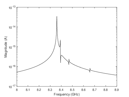
Axion current $I_a$ of the cylindrical cavity as a function of the frequency, considering the total set of modes coupled with the coaxial probe ($M=6$). Magnitude (top) and phase (bottom) are displayed.
Extracted $P_w$ and dissipated $P_c$ powers of the cylindrical cavity as a function of the frequency, considering the full set of modes coupled with the coaxial probe ($M=6$) in comparison with \cite{jackson} (top). In the bottom figure, we present a zoom of the plot in order to check the coupling regime achieved in the design of the coaxial probe, observing a very accurate critical coupling condition.
Scheme of the five cavities coupled all-inductive RADES haloscope. The coaxial cable has been inserted in the first cavity.
Reflection scattering parameter $S_{11}$ as a function of the frequency for the RADES haloscope. Magnitude (top) and phase (bottom) are shown.
Axion current $I_a$ as a function of the frequency for the RADES haloscope, as obtained with the method presented in this paper. Magnitude (top) and phase (bottom) have been plotted.
Extracted $P_w$ and dissipated $P_c$ powers as a function of the frequency for the RADES haloscope (top). In the bottom figure we present a zoom of the plot in order to check the coupling regime achieved in the design of the coaxial probe at the main resonance, observing a very accurate critical coupling condition.