 | Schematics of the LHC Run II collimation layout (prior to 2019)~\citep{bib:w2}. |
 | LHC collimators dominate the overall machine impedance at the top energy (plotted on the left -- real part of the dipolar impedance as a function of frequency). They are responsible for nearly all the octupole current required to stabilize the beam, with $\sim50$\% coming from 11 secondary betatron cleaning collimators (plotted on the right -- estimated octupole threshold with a factor |
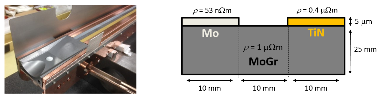 | The prototype collimator has two 10~mm wide low resistivity (Mo and TiN) stripes on a MoGr substrate. Left - photo of the collimator assembly; right - schematic drawing of the collimator jaw. |
 | The raw tune measurement data shows a clear reduction of the tune shift with the new materials with respect to the CFC. A significant tune drift during the measurement, not related to the collimator movement, can also be seen. The orange line depicts the position of the jaws (full gap) of the standard CFC secondary collimator, the blue line -- the prototype collimator. Black dots show individual tune measurements. |
 | The use of uncoated MoGr (red) reduces the resistive wall tune shift compared to the uncoated CFC (blue); each type of coating: TiN (green) and Mo (yellow) further improves the conductivity and can be clearly differentiated. For most materials the results are within 10-20\% of the model predictions (dotted lines). Dots and triangles show the measured data obtained for the nominal intensity of $1.2 \times 10^{11}$~p and the high intensity of $1.9 \times 10^{11}$~p (scaled down to the nominal intensity) respectively. The dashed curves represent Eq.~(\ref{eq:2}) fits with their $\pm 1$~rms uncertainties. |
 | SEM imaging \citep{bib:th15} reveals that Mo coating is not uniform: it has a column-like fine structure (left) and inhomogeneities up to 10~$\mu$m on its surface (right) that may affect the measured tune shift. |
 | SEM imaging \citep{bib:th15} reveals that Mo coating is not uniform: it has a column-like fine structure (left) and inhomogeneities up to 10~$\mu$m on its surface (right) that may affect the measured tune shift. |
 | Impedance of LHC collimators has to be reduced for the HL-LHC upgrade. It is responsible for nearly all the octupole current required to stabilize the beam at the top energy, with $\sim50$\% coming from 11 secondary collimators. Dashed line shows the hardware limit of 570~A and dash-dotted line -- a factor 2 operational margin. $E = 7$~TeV, Bunch Compression, Merging and Splitting (BCMS) beam, Ultimate operational scenario \citep{bib:w9}. |
 | SEM imaging \citep{bib:th15} reveals that Mo coating is not uniform: it has a column-like fine structure (left) and inhomogeneities up to 10~$\mu$m on its surface (right) that may affect the measured tune shift. |
 | The use of MoGr (red) reduces the resistive wall tune shift compared to the uncoated CFC (blue); each type of coating: TiN (green) and Mo (yellow) further improves the conductivity and can be clearly differentiated. For most materials the results are within 10-20\% of the model predictions (dotted lines). Dots and triangles show the measured data for $1.2 \times 10^{11}$~p and $1.9 \times 10^{11}$~p; dashed curves – Eq.~(\ref{eq:2}) fits with their $\pm 1$~rms uncertainties. Data taken at high intensity scaled down to the nominal one. |
 | A resonant wire measurement of the jaw impedance was performed at different locations along the jaw in a test stand prior to the installation of the prototype in LHC~\citep{Biancacci:2018cxa}. The difference in the real part of the longitudinal impedance with the respect to the uncoated bulk, depicted by lines and error bars, suggests a larger than expected resistivity of the Mo stripe for all tested frequencies: 68.5~MHz (blue), 591.0~MHz (red), and 869.8~MHz (green). The expected values are based on numerical simulations with IW2D \citep{bib:th11} and shown by stars. |
 | Resistive wall (left) and geometric (right) contributions of individual collimators to the overall dipolar effective imaginary impedance of the machine. Top energy $E = 7$~TeV, $\beta^* = 41$~cm, $Q' = 10$, Beam 2. Beam 1 collimators have similar impedance. |
 | 3D jaw layout of the novel secondary collimator design \cite{fedeColUSM}. |
 | Low-impedance secondary collimators decrease the machine's horizontal dipolar impedance (real part plotted along the vertical axis) at the top energy by 30\% at the frequencies around 1~GHz, relevant for the single-bunch coherent beam dynamics. Coating a subset of four collimators provides a half of the reduction. Energy 7~TeV; higher order modes (HOMs) of HL-LHC crab cavities not shown for simplicity. |
 | The collimator upgrade is expected to increase the TMCI threshold at the top energy by nearly a factor of two in HL-LHC (blue) compared to LHC (red). The measured mode frequency shifts (error bars) are in good agreement with simulation predictions (dotted lines). Beam~1, $E = 6.5$~TeV, $Q' = 5$ \citep{bib:w17}. |
 | Low-impedance secondary collimators decrease the machine's horizontal dipolar impedance at the top energy by 30\% at the frequencies $\sim~1$~GHz, relevant for the single-bunch coherent dynamics. Coating a subset of four collimators provides a half of the reduction. Chromaticity $Q' = 0$; 7~TeV; narrow spikes near 1~GHz correspond to the higher order modes (HOMs) of HL-LHC crab cavities. RF frequency shown by a dashed line. |
 | Novel coatings significantly improve the single beam octupole threshold. For the most critical BCMS beam up to $\sim 320$~A is gained by upgrading 9 secondary and 2 primary collimators per beam in the present baseline (``HL-LHC Baseline'') compared to the current machine (``Present Machine''). ``LS2 Upgrade'' reflects the situation in Run~3 with 2 primary and 4 secondary collimators upgraded; it provides over a half of the overall improvement, about 250~A. $E = 7$~TeV, $Q' = 10$, the situation in the most critical, horizontal plane is shown, assuming a factor 2 from the operational experience. |
 | Schematics of the LHC collimation layout \citep{bib:w2}. |
 | Breakdown of the overall dipolar effective imaginary impedance of the machine after the low impedance collimator upgrade by the individual collimators: resistive wall contributions are shown on the left and geometric -- on the right. The upgrade includes 2 primary and 9 secondary collimators per beam. Simulations in IW2D \citep{bib:th11}, top energy $E = 7$~TeV, $\beta^* = 41$~cm, $Q' = 10$, Beam 2. Beam 1 collimators have similar impedance. Primary collimator names begin with `TCP', secondary -- `TCSG', tertiary -- `TCT'. |
 | A simple round transition follows closely the optimal shape (left) and provides a near-optimal reduction of the geometric broadband impedance in the whole range of collimator openings of interest (right). 5.71~deg transition of the LHC secondary TCSPM collimators with $L = 80$~mm, $w = 80$~mm. |
 | A slow tune jitter with a $\sim 100$~s period and an rms spread of (thin grey lines) is observed during |
 | By correcting for the tune jitter one can achieve tune resolution of $\sim 10^{-5}$ and clearly distinguish the tune shift created by low impedance coatings. Tune measurements for the collimator jaws open and closed: top –- before, bottom -– after the correction. TiN stripe, $4.5\sigma$ halfgap. Solid lines represent 1 rms deviation from the mean (dashed lines). |
 | Novel coatings provide sufficient stability margin both for standard and BCMS beams. For a standard beam $\sim 120$~A is gained by upgrading all the secondaries in IR7 to Mo-coated MoGr and additional $\sim 30$~A – by replacing the two baseline primary collimators with MoGr. The situation in the most critical, horizontal plane is shown. |
 | Transverse impedance as a function of half-gap in mm from CST \citep{bib:CST} simulations of the current TCSG taper (green dots), the TCSP taper (red dots), or the TCSPM taper (blue dots) compared to the flat taper theory \citep{bib:th12} used for the model (black dashed line); solid lines represent extrapolation of simulation data toward small gap heights, where numerical simulation becomes computationally intensive. Subplot in the top right corner focuses on the difference between the model and the simulation results at large gaps. |