CERN Accelerating science

 
Sliced view of CMS detector highlighting (in Red) the location of the GE1$\slash$1 in the pseudo-rapidity region $1.6 <\left|\eta\right|<2.1$~\cite{cmsTdr}.
Evolution of GE1$\slash$1 detector since 2010~\cite{cmsTdr} from generation-I to generation-X (2018).
Muon trigger rate at Level 1 with and without GE1/1 GEM chambers and additional GEM chambers GE2/1 and ME0 described in reference~\cite{cmsTdr02}.
(top) GE1$\slash$1 layout and final design. The main components from bottom: drift board mounted all around with stainless steel pull-outs used for stretching of GEM foils, 3 mm frame, first foil, 1 mm frame, second foil, 2 mm frame, third foil, 1 mm frame, first O-ring, external frame, second O-ring and the readout board, (bottom-left) two detectors connected back to back to form a GE1/1 `super-chamber', and (bottom-right) map of the readout board showing 24 ($\eta$, $\phi$) sectors of GE1$\slash$1 chambers.
Design of the setup used for gain measurements using an X-ray tube, with a GE1$\slash$1 detector inside the copper chamber. The copper chamber is compeletely closed when the detector is exposed to X-rays.
Gain and rate measurements of sixth generation chamber (GE1$\slash$1-VI) while reading a particular ($\eta$, $\phi$) = (5, 2) sector. The error bars on the measured rate are Gaussian one sigma uncertainties which are very small and hence are multiplied by a factor of 25 ($\sigma$ $\times$ 25) so as to be visible on the rate curve.
(top) Gain of fourth generation GE1$\slash$1-IV detector for the gas mixtures Ar$\slash$CO$_{2}$ (70$\slash$30) and Ar$\slash$CO$_{2}$$\slash$CF$_{4}$ (45$\slash$15$\slash$40). (bottom) Observed gains of fourth generation GE1$\slash$1-IV and sixth generation GE1$\slash$1-VI detectors for Ar$\slash$CO$_{2}$$\slash$CF$_{4}$ (45$\slash$15$\slash$40). Points represent the data and the solid lines a fit to the observed data. The ratio plots have been calculated by fitting observed data and using the fit equations to interpolate into the regions of missing data points while taking the ratio between the gains corresponding to Ar$\slash$CO$_{2}$ and Ar$\slash$CO$_{2}$$\slash$CF$_{4}$.
(top-left) Schematic of the beam test setup showing the direction of the muon beam, triggering scintillators (photo multiplier tubes (PMTs)) (in dark gray color), 10 cm $\times$ 10 cm tracking GEMs (in yellow), and GE1/1 chambers (in green)~\cite{five00}, (top-right) design of the tracking telescope showing three triggering scintillators (in grey color), 10 cm $\times$ 10 cm tracking GEMs (in yellow color), (bottom-left) movable aluminum stand holding GE1$\slash$1 chambers in front of the tracking telescope during the H4 beam test campaign, and (bottom-right) one of the earliest (December 2014) beam test setups at the CERN SPS.
Design of the setup used for gain measurements with X-ray tube and the GE1$\slash$1 detector inside the copper chamber. The copper chamber is compeletely closed when the detector is exposed to X-rays.
(top-left) Schematic of the beam test setup showing the direction of the muon beam, triggering scintillators (photo multiplier tubes (PMTs)) (in dark gray color), 10 cm $\times$ 10 cm tracking GEMs (in yellow), and GE1/1 chambers (in green)~\cite{five00}, (top-right) design of the tracking telescope showing three triggering scintillators (in grey color), 10 cm $\times$ 10 cm tracking GEMs (in yellow color), (bottom-left) movable aluminum stand holding GE1$\slash$1 chambers in front of the tracking telescope during the H4 beam test campaign, and (bottom-right) one of the earliest (December 2014) beam test setups at the CERN SPS.
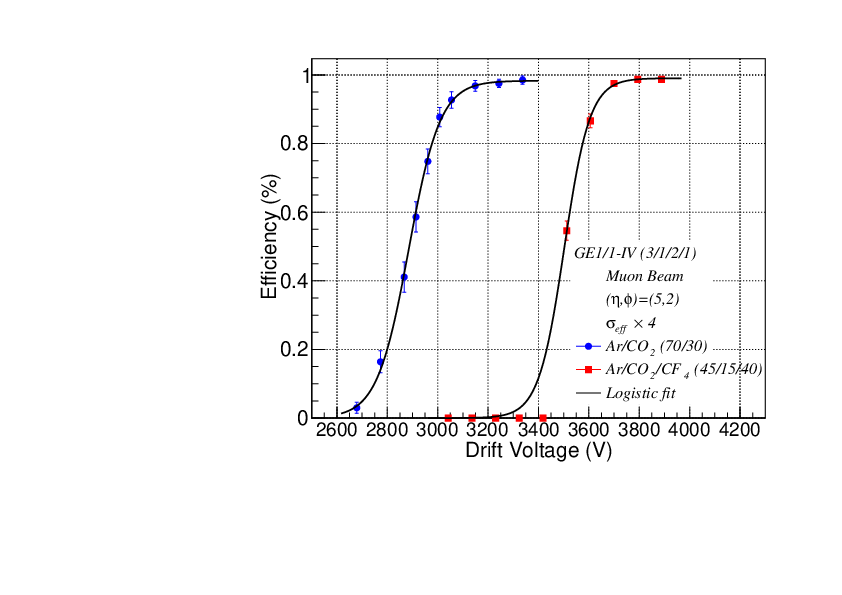
(top-left) GE1$\slash$1 chamber mounted with 24 VFAT chips, (top-right) efficiency, and (bottom) time resolution of a GE1/1-IV detector for the gas compositions Ar$\slash$CO$_{2}$ (70$\slash$30) and Ar$\slash$CO$_{2}$$\slash$CF$_{4}$ (45$\slash$15$\slash$40). Points represent the data and solid lines represent parameterized fits (details in Table~\ref{table:01}). The error bars on data represent Gaussian one sigma uncertainty. Since the uncertainty is small, for display, the errors are multiplied by a factor of 4 ($\sigma_{eff}$ $\times$ 4).
(top) Time resolution for Ar$\slash$CO$_{2}$ (70$\slash$30) and Ar$\slash$CO$_{2}$$\slash$CF$_{4}$ gases as a function of gain. The fit equations from Figure~\ref{fig:Efficiency} (bottom) are used to obtain data points by interpolation; the solid lines connect the points. The ratio of time resolution for Ar$\slash$CO$_{2}$$\slash$CF$_{4}$ (45$\slash$15$\slash$40) to Ar$\slash$CO$_{2}$ (70$\slash$30) is shown in same plot. (bottom) Rate capabilities of a GE1$\slash$1-IV chamber and, for comparison, a 10 cm $\times$ 10 cm test detector. The shaded ``\texttt{CMS Region}" spans the range of particle flux expected in CMS for HL-LHC.
Discharge probability for the gas composition Ar$\slash$CO$_{2}$.
Master plot of GE1$\slash$1 detectors showing the gain (pink), discharge probability (black), efficiency (red), and time resolution (blue) for the gas composition Ar$\slash$CO$_{2}$ (70$\slash$30) as a function of drift voltage. The axes and corresponding data are represented by the unique color code in the plot. Also, the plot shows the shaded region that is the recommended operational region of the chambers during their use in CMS.
Master plot of GE1$\slash$1 detectors showing the gain (pink), discharge probability (black), efficiency (red), and time resolution (blue) for the gas composition Ar$\slash$CO$_{2}$/CF$_{4}$ (45$\slash$15$\slash$40) as a function of drift voltage. The axes and corresponding data are represented by the unique color code in the plot. Also, the plot shows the shaded region that is the recommended operational region of the chambers during their use in CMS.